- Have Revised
Introduction to Chemical Sensors
Let’s start with a few definitions:
Chemical Sensor - A device that transforms chemical information, ranging from concentration of a specific sample component to a total composition analysis, into an analytically useful signal
Analyte - Substance or chemical constituent that is undergoing analysis
Concentration - The amount of chemical in a fixed volume, typically measured in Molar (1 Molar = 1 mol/litre)
What is the Chemical Sensor’s importance to medicine?
Good for medical diagnosis and treatment as the body is full of chemical markers: DNA, glucose, pH, lactate.
Chemical sensors are small-sized devices comprising a recognition element, a transduction element, and a signal processor capable of continuously and reversibly reporting a chemical concentration.
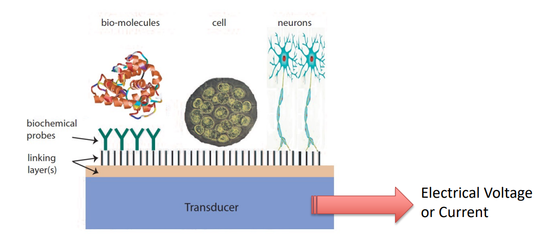
- Recognition Element - Something which combines the molecule
- Transduction Element - Something which converts whatever happened into a voltage or current
- Signal Processor - Capable of continuously and robustly reporting a chemical reaction
Desirable and Undesirable Attributes and Characteristics
We have some attributes that chemical sensors should generally have:
- Transform chemical quantities into electrical signals
- Respond rapidly to changes in concentration
- Maintain their activity over along time period
- Be small to help deployment.
- Be cheap to make them affordable.
- Be specific ,i.e. they should respond exclusively to one analyte, or at least be selective to a group of analytes.
And we also have some more specific desirable characteristics:
Signal Response: Output signal should ideally be linearly proportional to target species concentration and noise-free
This is because we need to characterise the O/P voltage to a specific molecule. This means we can equate an increase of current to that of concentration of the molecule in molars.
If it is non-linear, it makes it difficult to determine our molecule concentration
Response Time: Fast response times are desirable since slow sensor response can limit the use in real-time monitoring applications
Signal-to-Noise Ratio (SNR): The ratio of total signal response to limit of detection (LOD) of target species, the SNR is ideally high
SNR reflects the limits of detection, we ideally want it very high
You can effectively think of it as the resolution of your chemical sensor
Selectivity: Ideally a sensor should be highly selective, i.e. its signal output originates only from the target species and not from interfering species.
Sensitivity: Defined as the change in signal per unit change in concentration, the sensitivity should be high to discriminate accurately and precisely between small differences in analyte concentration
Below are our undesirable characteristics:
Non-linearity: Response is not proportional to the input signal
Slow response: Output is slow to reach a steady-state value
Small working range: Operating range is restricted
Low sensitivity: Sensor can only respond to large input signals
Low selectivity: Interference from other species affects sensor output
Baseline drift: Output varies with time
When we put a solid sensor in contact with liquid, when the first contact happens an equilibrium process takes place between a solution and the chemical recognition process.
Within that you have some thermodynamics, an exchange of ions
The net result is that sensors inherently drift, if it’s linear it’s ok but if not it’s hard to compensate for
Sensitivity drift: Sensitivity varies with time (e.g. due to temperature change)
- Slope changes over time, making it difficult to recognise molecule concentration.
Ageing: Sensor output changes with time
Interference: Output is sensitive to external conditions, e.g. stray electromagnetic radiation, humidity, etc.
Hysteresis: Systematic error in the input-output curve
- Following different trend to return to original concentration, making it difficult to determine sensor O/P
Noise: Output contains an unwanted random signal
Types of Chemical Sensors
There are a number of categories of chemical sensors:
Electrochemical sensors: based on the measurement of redox chemistry of chemical species; among them voltammetric and potentiometric devices, chemically sensitized field effect transistor (CHEMFET) and potentiometric solid electrolyte gas sensors
Electrical sensors: based on the measurement of a change of electrical property of a device; include those with metal oxide and organic semiconductors as well as electrolytic conductivity sensors
Optical sensors: based on the measurement of light ; include those following absorbance, reflectance, luminescence, fluorescence, refractive index, opto-thermal effect and light scattering.
Mass sensitive sensors: based on the measurement of a change in mass ; include piezoelectric devices and those based on surface acoustic waves
Magnetic sensors: (mainly for oxygen) based on paramagnetic gas properties
Thermometric sensors: based on the measurement of the heat effect of a specific chemical reaction or adsorption which involves the analyte
There are also other sensors, mainly based on emission or absorption of radiation.
Electrochemistry
Electrochemistry is the study of redox chemistry of chemical species and the potentials and currents associated with them.
We make measurements IN electrochemical cells consisting of 2 or more electrodes and the electronic circuitry for controlling and measuring the current and potential.
The concentration of the analyte is normally transduced as a voltage or current depending on what type of measurement you conduct
Redox Reactions
Redox reactions (reduction-oxidation reactions) are chemical reactions where electrons are transferred between atoms, molecules, or ions.
- Oxidation - Loss of electrons
- Reduction - Gain of electrons
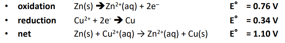
Example of Oxidation:
Here zinc loses 2 electronis and becomes a ion. We must add the 2 electrons to balance the equation.
Example of Reduction:
Here, copper ions gain two electrons to form copper metal, so it’s reduced.
- Oxidizing Agent: Substance that is reduced and helps another to oxidize.
- Reducing Agent: Substance that is oxidized and helps another to reduce.
The Galvanic Cell
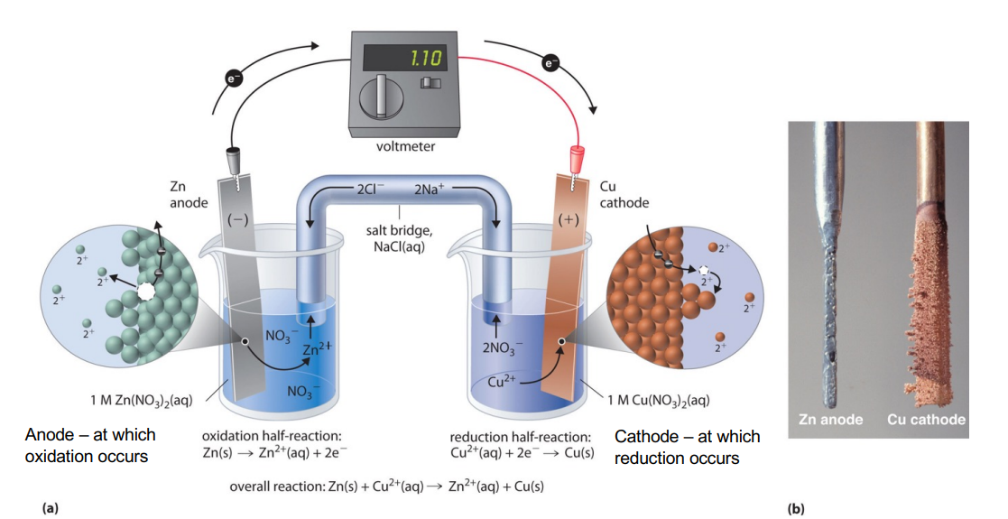
The galvanic cell converts chemical energy into electrical energy via spontaneous redox reactions.
This involves 2 electrodes:
- Anode - The electrode where oxidation (loss of electrons) occurs
- Cathode - The electrode where reduction (gain of electrons) takes place
Each electrode is placed in an electrolyte solution containing ions related to the electrode material. For example, if one electrode is made of zinc, the electrolyte may contain zinc ions ().
A salt bridge maintains electrical neutrality in the solutions by allowing ions to move between the two electrolyte solutions without directly mixing. It prevents the build-up of charge that would otherwise stop the flow of electrons.
How it works
- Spontaneous redox reaction occurs, species at anode loses electrons (oxidation) while species at cathode gains electrons (reduction)
- Electrons flow from anode to the cathode via an external wire, this generates a current so we can measure potential difference
- to maintain charge balance ions in electrolyte move via salt bridge.
This specific example is that of a Zinc-Copper Galvanic Cell.
- Anode (Zinc electrode): Zinc metal () loses two electrons and becomes ions, which go into the solution.
- Cathode (Copper electrode): Cu²⁺ ions in solution gain two electrons to form copper metal (Cu), which plates onto the cathode.
The overall reaction is:
Redox Potential
In electronics we measure the voltage relative to ground whereas in chemistry they measure it relative to what’s called the standard hydrogen electrode (SHE).
Therefore the potential of each ion has been determined with reference to the SHE
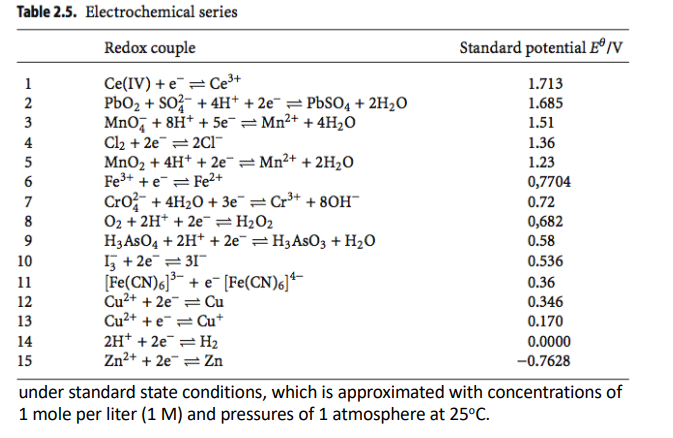
This table allows us to take our 2 known metals and calculate what the voltage will be when we put them together
To calculate the electrode potential of an electro chemical cell in non-standard conditions, we use the following Nernst Equation
Where:
- is the electrode or cell potential under non-standard conditions
- is the half cell standard potential
- is the concentration of oxidised species
- is the concentration of reduces species
- is the number of electrons
- is the temperature in Kelvin
- and are the universal gas constant and Faraday constant respectively
Example
The net reaction of a voltaic cell constructed from a standard zinc electrode and a standard copper electrode is obtained by adding the two half reactions together (See table)
Principles of Electrochemical Sensors
Let’s look at the main categories of electrochemical measurement:
Potentiometry
This refers to the measurement of potential difference generated between an ion-selective electrode (ISE) - an electrode selected to the ions you’re looking for - and a reference electrode.
The potential difference between them is caused by a difference of concentration between the sample (analyte) solution and a reference solution
This gives you an indication as to what ion your ISE is selective to
Voltammetry
This refers to imposing a voltage (waveform potential) onto the electrodes (reference electrode)
If that voltage hits the redox potential, they’ll start to generate a current and you measure that current.
We do a voltage scan and check when the max current is O/P.
When the voltage is fixed, this is referred to as amperometry
Amperometry
This refers to applying a fixed potential to a reference electrode
This causes a species of interest to be oxidised or reduced and thus current flows between this electrode and a ‘working’ electrode
We therefore measure the current
Conductimetry
- We measure the conductance between electrodes
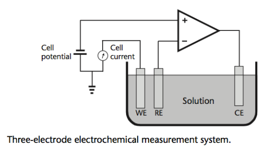
Naming of Electrodes
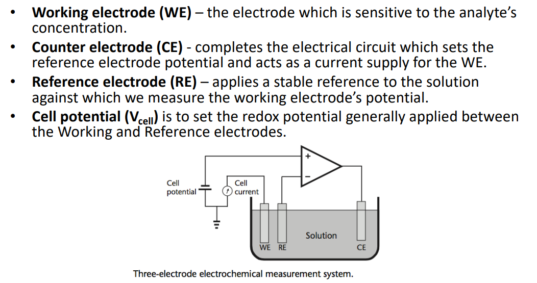
- The WE is always sensitive to the molecule you are looking for
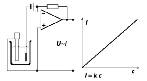
In this configuration, with the op-amp, it’s called a potentiostat
Cyclic Voltammetry
- Cyclic Voltammetry (CV) is one of the more powerful and widely used techniques in electrochemistry;
- It involves the study of the currents associated with redox reactions;
- When the potential is swept in a linear ramp, in both the forward and reverse directions, between two switching potentials.
- Used to provide a broad overview of the system- identify what’s there.
- Identify the operating potential for amperometry.
- Peak potential allows identification, peak height is proportional to concentration.
Typical Waveforms
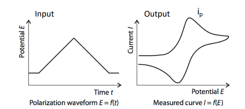
Here we do our sweep using a triangular wave, sweeping up and down. This is usually from 0-1V as post redox potentials are in the sub-volt range.
Then we get a current peak where the redox reaction happens.
- Potential at which the peak occurs identifies what there is
- Amplitude of peak identifies how much there is
Potentiostat
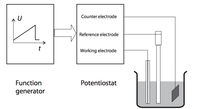
To carry out Cyclic Voltammetry and Amperometry we need a potentiostat. It applies dynamic voltage onto the electrodes.
Peak Redox Current (Randles-Sevcik Equation)
In cyclic voltammetry, when a potential is applied to the electrode, an oxidation or reduction peak appears in the current vs. voltage plot (voltammogram). Using the Randles-Sevcik Equation, the peak current can be analyzed to extract information about the species in solution and the nature of their interaction with the electrode surface.
- = number of electrons transferred/molecule
- = electrode surface area (cm2)
- = concentration (mol/cm-3)
- = diffusion coefficient (cm2 s-1)
- = scan rate (V/s)
Important to consider when designing the size of your electrodes and the maximum current you want to detect for a given concentration.
Amperometry
Unlike Voltammetry, in Amperometry we impose a fixed potential on the solution via the Reference Electrode.
If this potential is the redox potential of the analyte being measured, a redox reaction will start to occur. Electrons will be generated at the working electrode surface.
Current in the circuit is proportional to the rate of generation of electrons. Current is therefore proportional to the concentration of the analyte.
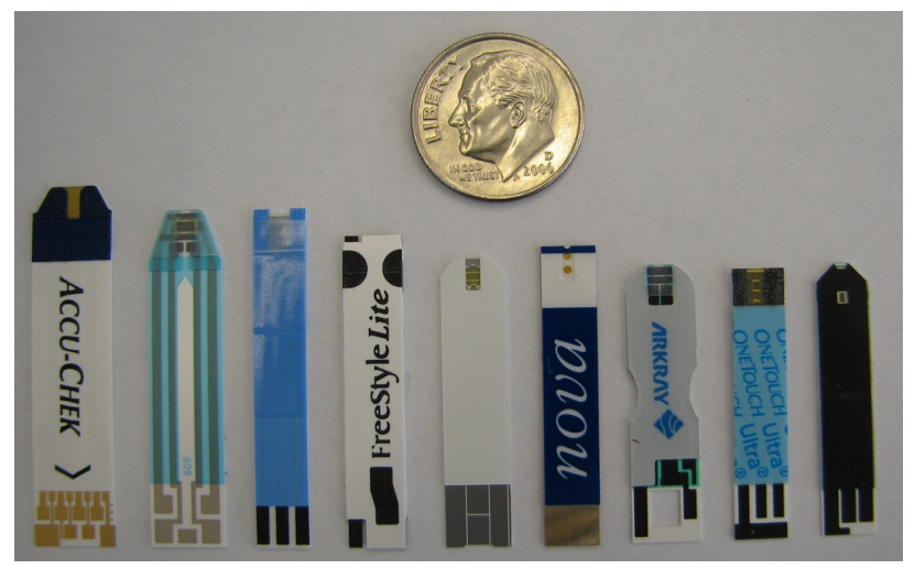
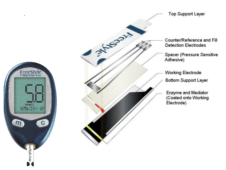
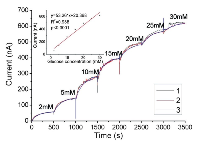
The most common amperometric sensor is a glucose sensor. The working electrode is the one that identifies the glucose. There’s no surprise therefore it is the biggest as we want to maximise the current.
Here we can see a typical dose response. We are used to having linear curves but every time the concentration is changed, it takes time for the concentration to settle.
Circuitry
So we’ve established for amperometry we need something to apply a fixed potential and something to measure current. Therefore we have some requirements:
- Requires current to flow through a fixed solution potential
- Voltage must be stable and not fluctuate with changing current
- Current must be buffered for further processing / conversion (e.g a A/D converter)
Below is the typical architecture:
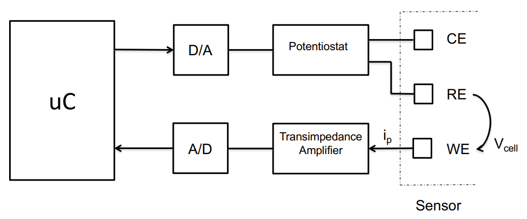
So we have:
A potentiostat to apply the fixed redox potential to establish the between the reference and working electrode
A microcontroller and D/A converter which allows us to program what that voltage is
A transimpedance amplifier which measures the amount of current flowing through the working electrode and then converts it into something to put into an A/D converter, which is then sampled with the microcontroller
Potentiostats
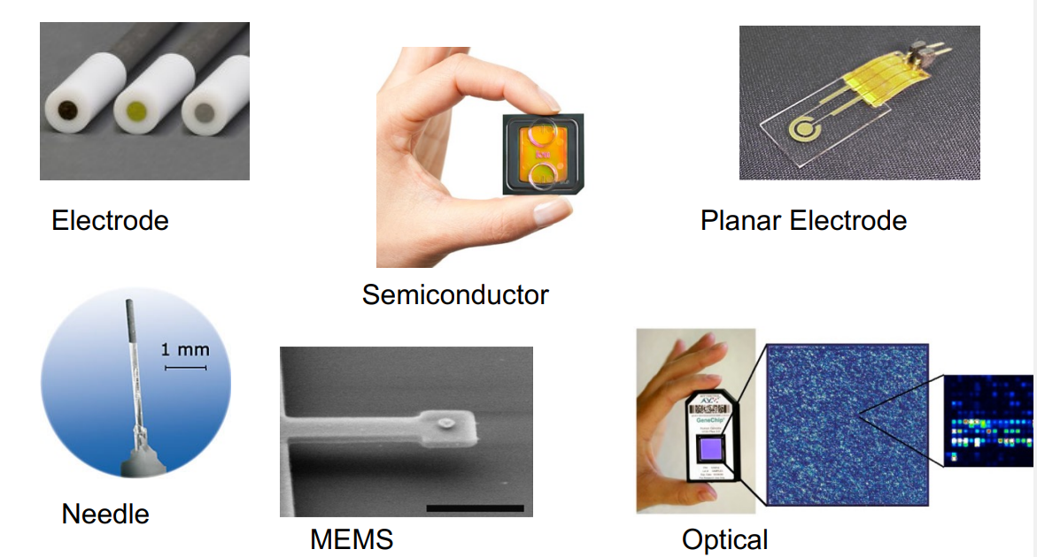
Electrodes
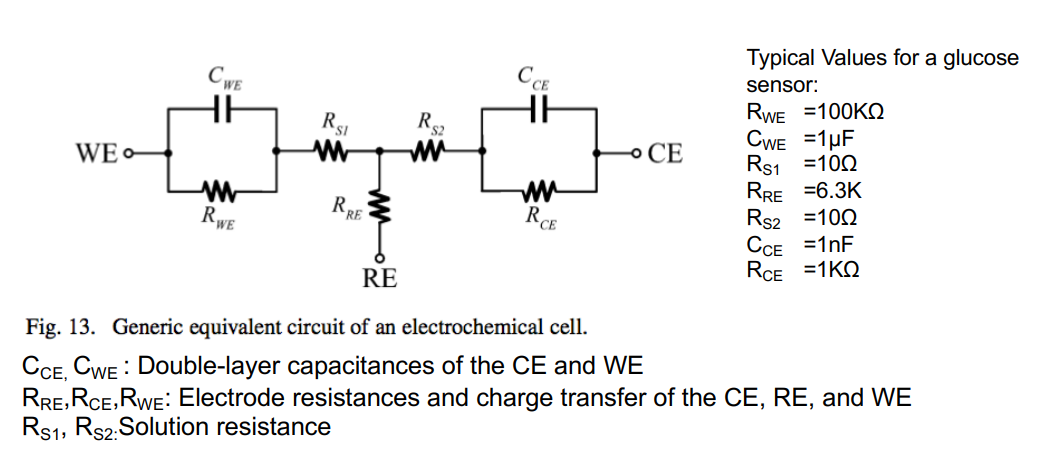
Before we go about designing circuit, we should first get an indiction of how these electrodes work at a surface level:
Similar to last week when we looked at interfaces, we can represent an electrochemical cell as a grouping of resistors and capacitors.
NOTE: THIS IS JUST FOR MODELLING PURPOSES
Biasing the Solution
We need to apply a fixed voltage between the reference and working electrode. It should come as no suprise you can use an amplifier.
Let’s break this circuit down:
- RE & WE should always be at a fixed stable potential.
- Control amplifier should be able to source/sink Redox current and establish a fixed closed loop potential.
- Voltage of chemical cell
- The voltage gain and input offset voltage of the control amplifier define the accuracy.
- Typically Gain > 104 and offset voltage < 10mV.
- Also need to consider output voltage swing and noise and bandwidth.
- With this configuration needs to be negative to establish positive .
So the problem with this configuration is that we have to input a negative cell potential to get the right . So for glucose .
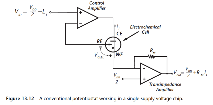
That might be ok if you were only using discrete systems, however if we are using CMOS ASIC, for example, then we only work with positive voltages so this circuit wouldn’t work. The solution is this circuit
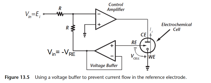
Let’s break this down:
- Allows application of a positive to establish a positive . ()
- Good when driving from a single supply DAC
- Minimal RE leakage through voltage buffer
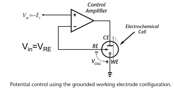
There are also implementations where you can ground the counter electrodes. This is often used to measure current, you can stick a differential instrumentation amplifier on the WE node and measure the current going through.
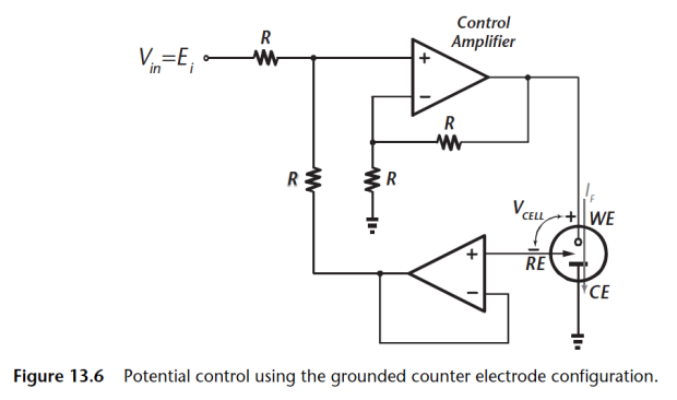
Let’s break this grounded CE implementation:
- Now have a grounded CE implementation
- Allows single supply operation
- WE is susceptible to noise and interference
- Cannot supply multiple working electrodes
Again the problem with this circuit is that the WE now picks up all the noise from the control amplifier. Also you cannot supply multiple WEs, this means if you want an array of electrodes in this configuration you can but not in the one above.
Current Measurement
How do we satisfy the requirement that we need at a ground node, and be nice and quiet, but also measure current?
You put what’s called a Trans-Impedance Amplifier
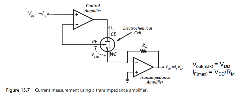
So what does this circuit do?
- Transimpedance Amplifier - Converts current to voltage through a buffered resistor.
- WE sits at virtual ground
- Resistor size must be chosen so as not saturate the amplifier and maximise dynamic range
- R_M can be programmable and have a tunable gain allowing measurement of very small current
However we have some drawbacks:
- Resistor can add thermal noise to measurement. This is a problem when trying to measure small currents with large resistors
- Large resistors are generally difficult to realise in ASICs
- WE is at a virtual ground and thus susceptible to noise and interference pick up
So to avoid using a large resistance we can instead use a capacitor implementation
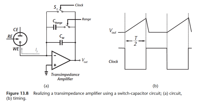
Here’s what we’ve done:
- Switched to Capacitor implementation
- Sensor current charges up capacitor.
- Does not need resistors which take up a lot of space when large
- To measure small currents we can just increase the clock period !!
- Can add programmable gain through
The beauty of this circuit is that we no longer need big resistors, you can tune the impedance of the network according to the period of your clock, so you can measure really small currents, just increase the clock periods.
Some More Potentiostats for Reference
Here’s some more potentiostats for reference and example (likely not in exam):
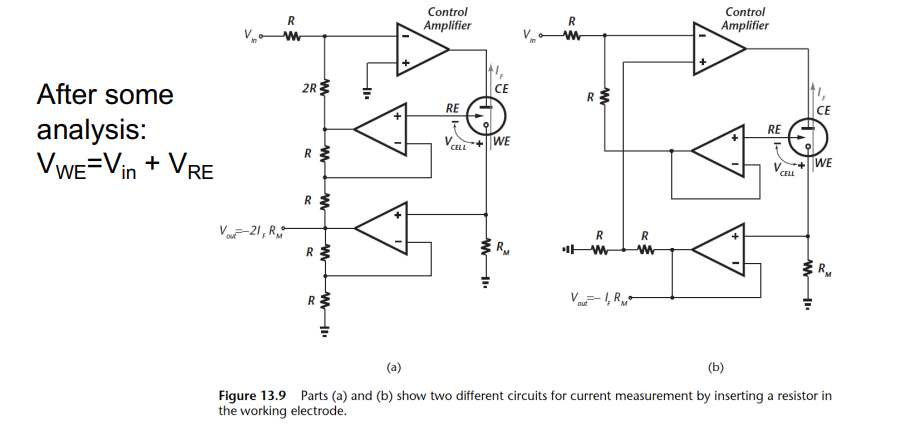
Here’s one (on the left) where you can measure again from the working electrode through a resistor.
In order to maintain at a constant potential, we get a bootstrap circuit that ensures when the working electrode voltage changes it uplifts the left side’s voltage and inturn the reference voltage.
So effectively the potential is always shifting, but always constant in this circuit
On the right we have a similar topology that does exactly the same thing.
We also have the configuration mentioned before to do with adding a differential amplifier.
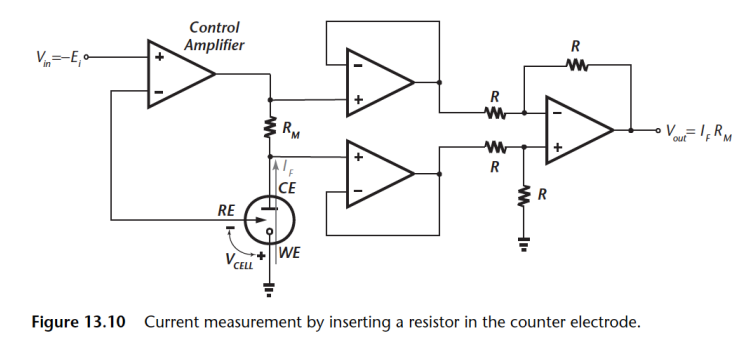
Here’s we insert a resistor in the current path of the CE, this way we can measure the voltage generated using an instrumentation amplifier.
The WE is connected to true ground so it is not vunerable to pick up AND there are NO active components in signal path so it has better stability.
The only limitation on this circuit is ensuring voltage generated doesn’t saturate the control amplifier
ASIC Implementation
When working with ASIC, the one thing you need to bear in mind is that ground is actually the common mode voltage, whch is typically .
- So if operating of a single supply, then need to operate everything with reference to .
- Need to guarantee a stable common mode voltage
- I/P drive voltage is limited to
Generating Voltage
The circuit below is how how we would generate the voltage on the chip. We need to ensure that there is stable voltage reference generation on chip.
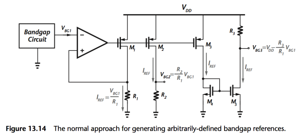
- We use a bandgap circuit to give a stable voltage reference, which is insensitive to temperature.
- Then we just have a bunch of current mirrors with resistors
- At each output of the resistance, we have a different voltage reference which can be used to drive the potentiostat
Potentiometry
Potentiometric is a measurement of votlages between a reference electrode and an ion selective electrode
What is an ion selective electrode?
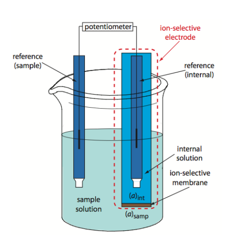
The ion-selective electrode is typically an electrode with an internal solution which is highly saturated and it measures the potential difference between that internal solution and the solution that you are measuring.
- It uses a membrane to establish a fixed potential
- There is a change in potential across a glass membrane when its two sides are in solutions of different concentration
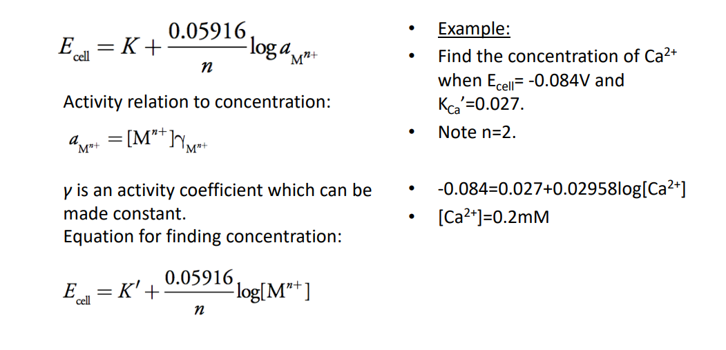
The voltage you measure can be given by the next equation. It is effectively a relation between the internal ions in the stable reference electrode, and the ions in your sample
Where:
- the analyte’s concentration (activity) in the sample
- the concentration (activity) of analyte in the ionselective electrode’s internal solution.
- the sum of constant redox constant potentials (it’s constant)
- or is the analyte’s charge
The max we can get out of this is called the Nernst potential at 59mV
At room temperature we can simplify the membrane potential equation by combining known constants into a single term .
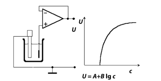
Here’s an example of how it works:
Circuit Requirements
So how do we measure that potential?
We need something that doesn’t allow a current to flow but can measure voltage.
- Need to emasure the Cell voltage
- Requires high I/P impedance and no disruption of the measured potential, i.e no current flow
- Use a high impedance transducing element like a MOSFET or OpAmp to measure the electric field generated
Solid State Ion-Selective Electrodes
We can use a transistor ITSELF as an ion-sensitive electrode. This is called an ISFET.
The ISFET is a MOSFET transistor whereby the gate becomes your ion-selective electrode
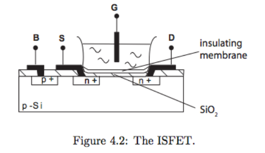
- It is a chemically sensitive transistor
- The chemical sensitivity arises due to an Ion-Selective Membrane deposited on the Gate
- Insulators such as can make it pH sensitive.
- A change in concentration causes a change in the devices threshold, which we can monitor
We can also put ionophores on the surface to make it sensitive to different ions. When we do this, they are called CHEMFETs.
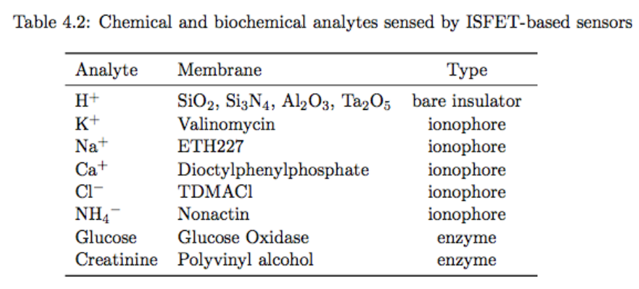
These can all be made in CMOS, meaning they are loss cost, can be mass-fabricated, they’re small, fast and integrate easily.
Challenges include, chemical sensitivity, sensor drift and failure and temperature dependence.
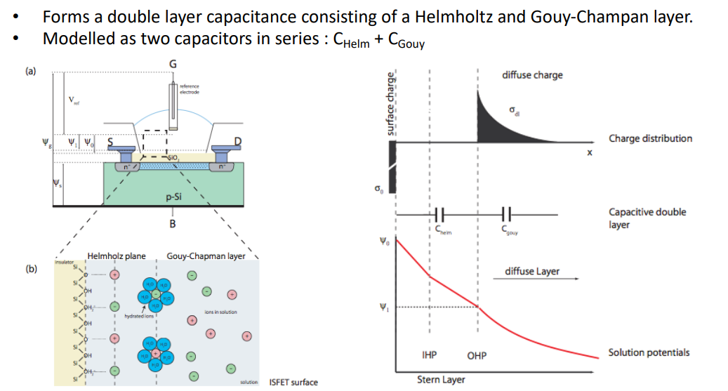
The sensing mechanism of the sensing membrane works as follows: some bio-chemical processes occur, which we can model as 2 capacitors in series. They produce a big amount of charge in the solution which gets reflected on the surface and causes the change in potential.
We can treat this whole process as a transistor, with the following macro-model:
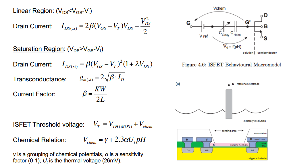
- All transistor equations remain the same in the linear region, saturation and gm
- The thing that changes is the threshold voltage, which changes based on ph
- This is defined at the bottom
Here’s what an ID VGS sweep looks like for different pHs:
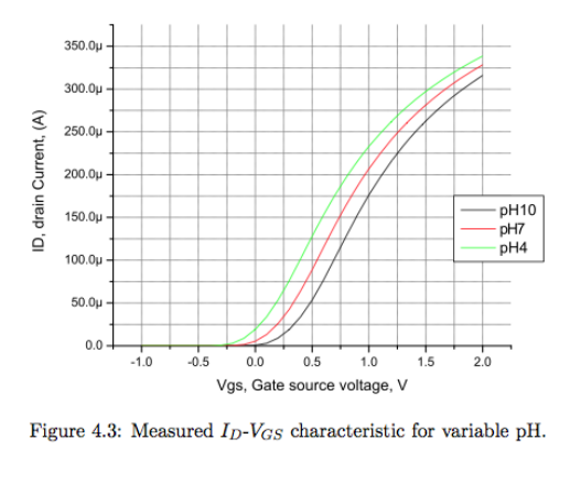
Therefore if you want to keep track of what the pH is, you either need to establish a fixed potential and measure the current output of the transistor or establish a fixed current and measure the change in voltage.
- Threshold voltage shifts with pH concenration.
- 1 pH unit causes a change of 59mV.
- This is known as the Nernst Potential - 59mV/pH
ISFET Readouts
WE want to measure the change in
We use the following circuit, this is called the Constant Charge Method (CCM), it is a Opamp based method:
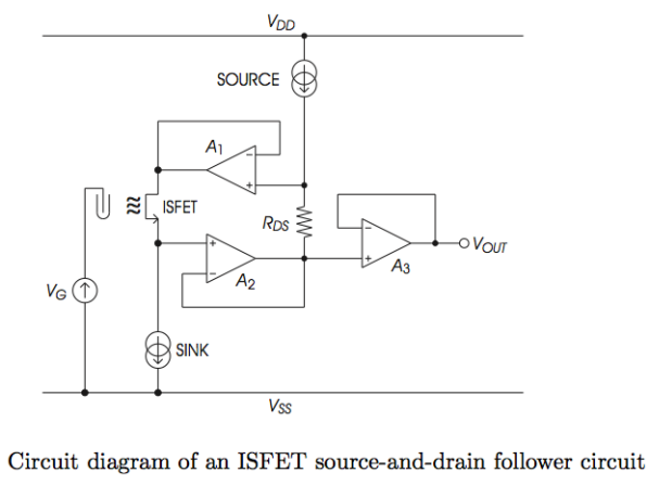
- Fix , , to operate at a fixed working point.
- then tracks changes in .
- Opamp tracks changes in and through feedback of , sets to ensure is always constant.
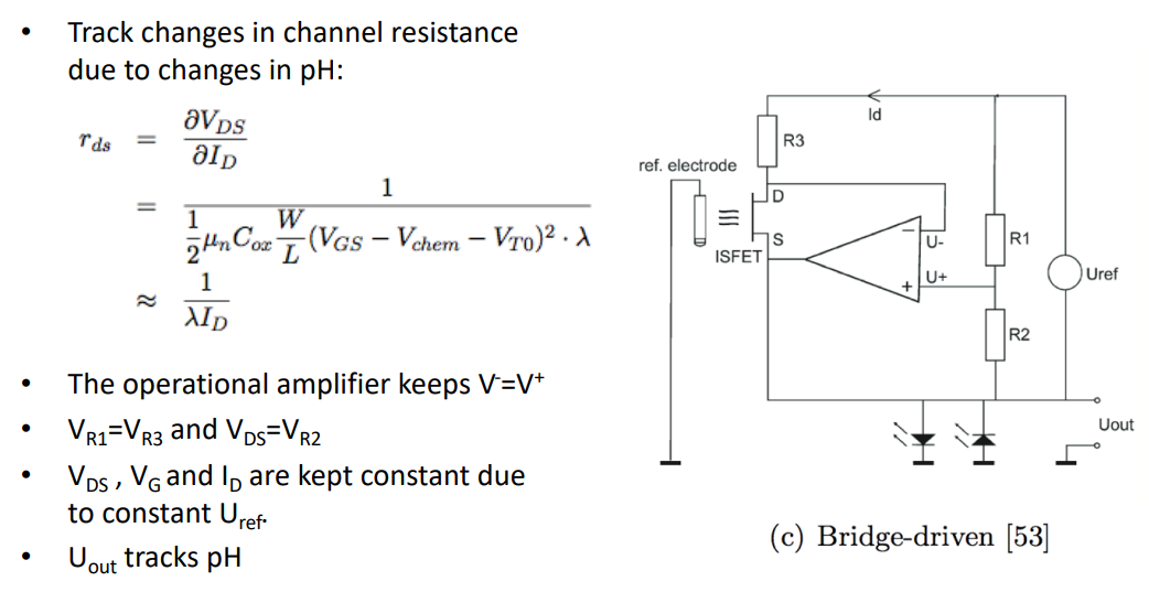
We also have a Bridge based method (referring to the wheatstone bridge resistor circuit):
And we also have an Instrumentation based method, looking back to last week’s instrumentation amplifier:
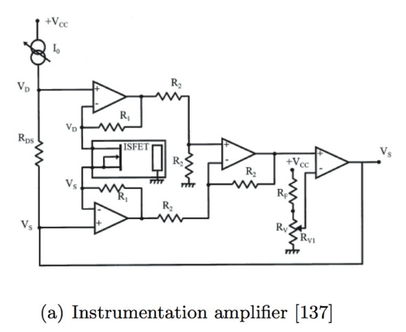
The ISFET is connected at the terminals usually applied to the gain- determining resistor.
The fixed voltage across the input terminals of the instrumentation amplifier (VDS) holds the ISFET drain- source voltage constant, and the gate- voltage is fixed by the grounded reference electrode.
Thus any change in ion concentration modulates the current through the ISFET, and thus its channel resistance.
The difference between this output and a fixed reference voltage acts as a feedback signal to adjust the common- mode level of VDS to keep the drain current constant and achieve constant charge mode operation.
Conductomety
Conductometric Measurement can be defined as follows:
- A change in concentration causes a change in the conductivity of the solution which we can measure.
- Measurement of the ability of a solution to carry electric current.
- Not very selective however as a solution can contain many ions.
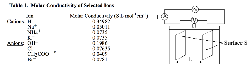
We want to measure the Conductance in units of or Siemens
The Conductivity:
Where:
- K () = cell constant based on...
- conduction length
- and cross sectional () area of electrode surface
- units or
And we use this to get more detail specifically on the conductivity of the solution, we call the Molar Conductivity
Where:
- is the measured conductivity,
- is the electrolyte concentration
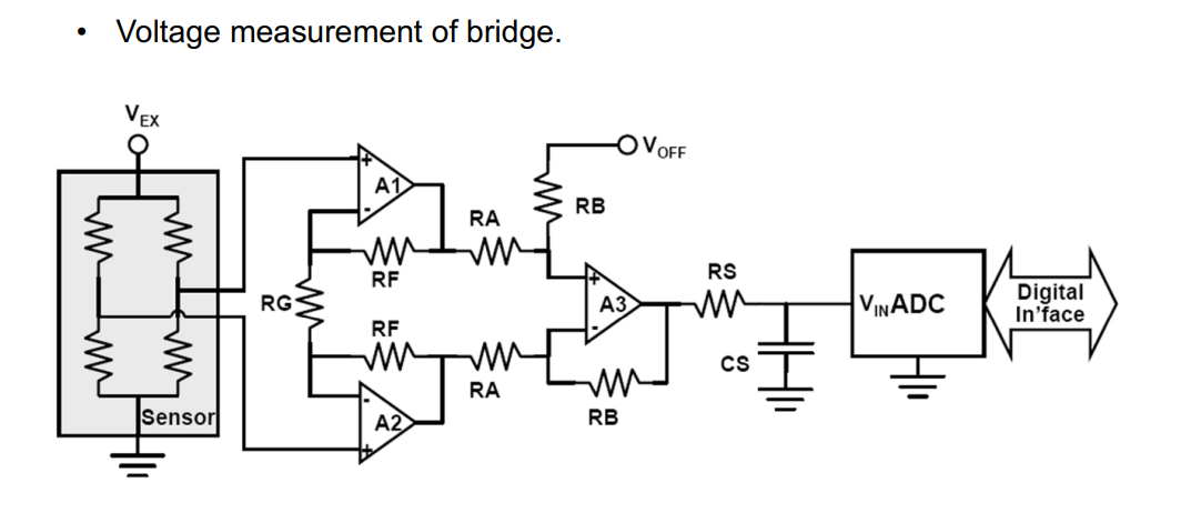
Wheatstone Bridge
How do we measure this resistance?
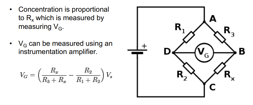
We use the wheatstone bridge circuit. We measure the voltage difference between the circuit bridge, this will give you an indiction of the solution conduction.
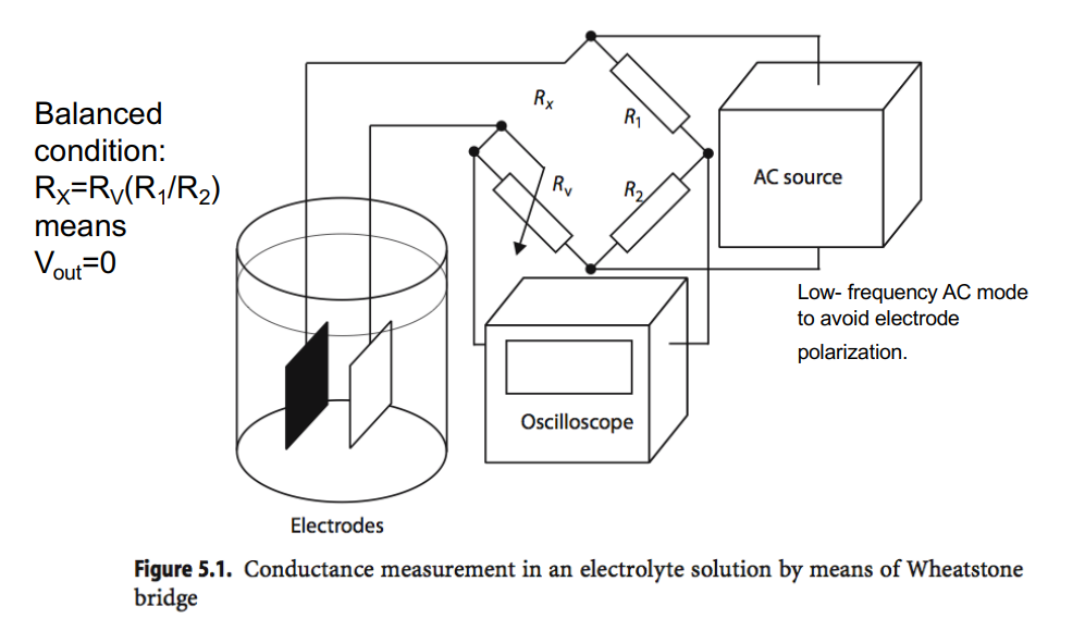
Below is a commonly used circuit, it’s a balanced configuration whereby if you measure , provided the resistor values , and are fixed it gives you an indication as to what is.
And how can we implement this?
We use a bog standard instrumentation amplifier, an LPF and then into a ADC.