- Have Revised
Introduction
This lecture looks at the challenge of powering medical devices. This is different to what we have covered so far which has largely been about low power analogue electronics and analogue signal processing.
With increased demands of ever more complex medical devices, there is a greater need for long lasting batteries. This trade-off is easier to manage for a mobile phone, for example, where you can charge it everyday, but for medical devices this can be a bigger problem - e.g implantable devices.
NOTE: This does not only apply for implantable devices, wearable devices that are essential for survival require sufficient power considerations also
Example: LVAD
The LVAD is a device which is used to assist an existing heart by pumping some of the blood itself. This is done to take some of the strain away from a damaged or strained heart, it’s particularly used when waiting for a heart donor is taking too long.
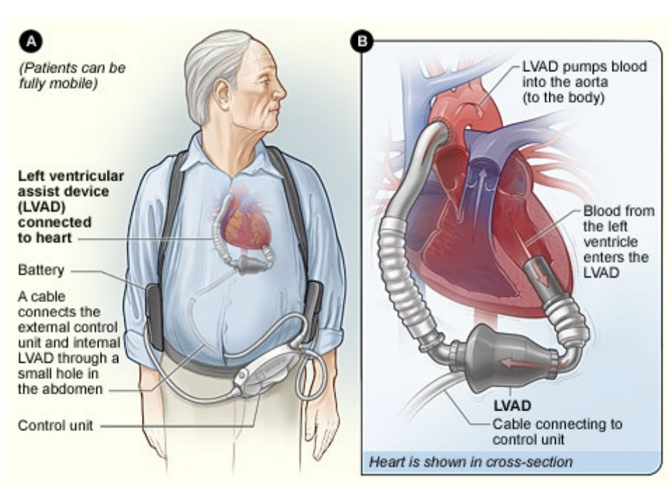
The pumps involved are actually generally incredibly reliable, the problem is power consumption.
Power consumption depends on human activity, if you’re sat or sleeping you require less power, if you’re up and walking you require more.
This means you could require between 5-10W continuously to pump blood around the body. This is quite high power.
So how do we get power to this device?
At the moment there is some external control unit that’s powered by some batteries which is slung over the patient’s shoulder. These can then be charged.
Power Solutions
So we’ve had a look at some of the problems encountered by biomedical devices with regards to powering them. What we’ve looked at so far (low power analogue electronics) is already a good step in solving those problems.
The most common solution for powering any kind of portable device is to use a battery because it has a finite energy supply you can measure. However for some applications batteries would simply be too large, so we have to look at other ways of powering these devices.
There are several ways to generate electrical power without using a pre-charged device like a battery. We will look at the following:
- Motion-Driven Energy Harvesting
- E.g the idea of a Seiko kinetic watch that is able to power itself via movement and oscillation of an internal mass which moves, charging a generator (low power devices)
- Thermoelectric Energy Harvesting
- E.g A TEC used for cooling a CPU, putting a series of back-to-back semiconductor junctions together to get thermal energy (low power devices)
- Wireless Power Transfer
- Or otherwise known as transcutaneous energy transfer
Energy Harvesting
There are a number of methods of energy harvesting, so why do we suggest the aforementioned methods?
- Solar - Getting energy from light
- Fuel Cell - Making use of the glucose in bloodstream
- Ambient RF - due to 4G and 5G base stations, WAPs, etc there is a lot of RF energy floating around, maybe you could try to use that energy?
The main issues with these are as follows:
Low availability - For whatever energy the method is attempting to harvest, it needs sufficient energy to power the device, this is not always possible.
- Solar, for example, has the issue of limited availability of light
Encapsulation - Need to consider the Biocompatibility of anything you put in the body, otherwise the body can reject it, causing inflammation and pain. The typical solution is to surround the device in a biocompatible material.
- The fuel cell, for example, does not work for this as you can’t fully encapsulate it, as it must interface with the blood.
For safety and encapsulation purposes, kinetic and thermoelectric devices look best
The General Medical Power Supply
The medical requirements for a general medical power supply are as follows:
- Very high reliability - Implants are often crucial for life of patient
- Long lifetime - Especially if implanted as to not require surgery
- Biocompatible - Material must not elicit undesirable local or systematic effects in the recipient
A typical medical device will have the following components that need powering:
- Sensor
- A/D Converter
- Signal Processing
- Transmitter
- Power Supply
NOTE: The communication is likely to dominate the power consumption
Transmitter
You have to consider when transmitting that when you decide a method of communication, for example Bluetooth, you’re buying into a whole protocol stack, and a whole load of energy associated with running a protocol stack.
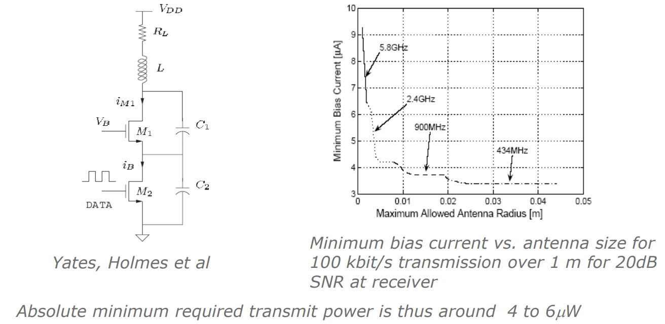
With that in mind we really want to minimise the power consumption of these devices. A simple concept for a transmitter is as follows, this is called a Colpitz oscillator transmitter:
Here is how it works:
- You put data into the MOSFET (could be simple on-off keying)
- The inductor acts as a loop antenna and for resonance with the capacitors
- This allows us to transmit data out
So the raw energy consumption needed to get data out of this circuit (without protocols and error correction) depends on the frequency you want to operate at as bigger antennas are needed for lower frequency.
From the graph we can see the relationship between the minimum bias current, and therefore the power consumption, and the antenna radius. We see that for higher frequency we need more power...
BUT we also see that this circuit only requires to run!
This is significantly more power effecient than using an off-the-shelf protocol like Bluetooth.
Sensor, A/D Converter and Actuator
We can get an idea of the other components of a medical device as well:
Sensors
- Temperature and pressure sensing can be done by measuring the voltage drop of a current through a resistor (with a resistor which changes with temperature or pressure).
- In principle, the power needs only to be sufficient to overcome thermal noise ( W/Hz at room temperature), and so can be negligible for the very low bandwidths of the application (as low as 1 Hz).
A/D Converter
- A/D converters have been reported with a power consumption of 1 µW at sampling rates of several k samples/s.
Actuation
- Actuation may require significant power.
- An insulin pump may consume mW when operating, and an artificial heart may require ~5 W continuously.
Putting it all together, how does it look?
So looking at 2 broad types of medical application:
- Sensor-only applications - Power requirements in the sub mW range, possible down to tens of s
- Actuation applications - Potentially tens of mW to several Watts, for an artificial heart.
A typical FDA approved, comercially available battery has energy densities of around 500 J/cm^3. This means you could run a 10 micro watt device for about 2 years before the energy is depleted.
For medical devices this is an issue - we can either make the device consume less power, or make the battery bigger.
Motion Driven Harvesters
We need a transducer to turn motion into electrical energy, the standard way of doing it is via some electromagnetic means. This usually means having a varying magnetic field linked to some winding that generates a voltage by Faraday’s law. Then from the voltage you get current flow and therefore electrical power.
There are other ways however, such as:
Piezoelectric - This essentially acts as a capacitor that charges itself as you bend or strain it
Changing the Geometry of a Variable Capacitor (Electrostatic) - When we apply too much voltage across a capacitor a force pulls the capacitor together, if instead we pull the plates apart we create a bigger electric field and can generate some energy from that
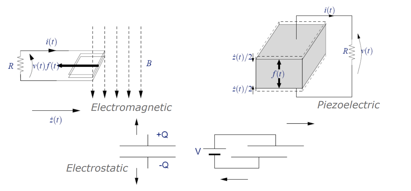
Electromagnetic is typically used for large scale power generation and actuation, but as you make devices smaller, this is not necessarily the best mechanism for power generation.
Some phenomena scale with length, some with area and some with volume and therefore you must pick which is best for each given use case. The actual scaling laws are too in-depth for this lecture but know that the electrostatic approach is becomes more powerful for smaller scales.
Microgenerator
So now we have looked at the possible ways of actually doing the conversion of kinetic to electrical energy, we now need to figure out how much energy we can get by employing one of those mechanisms
We have to do something in terms of force x distance, any work done by these movement driven generators is effectively just the integral of force x distance.
So as you run a current or battery into the device, that is providing a force x distance that us the maximum amount of mechanical power/energy going into the system. Therefore this equation gives us the limit on energy generation. This is then converted into some electrical form via some level of efficiency.
So how do we actually cause work to be done against one of our transduction mechanisms?
Take the electrostatic mechanism, we cannot physically grab hold of both capacitor plates and pull them apart while inside the body. It is more difficult to achieve actuation while devices are embedded in the body.
Outside of the body we can do something like this. This is called a direct-force driven generator.
Here we anchor both sides to two bits of the body that are going to move away from each other. On a small scale that is pretty difficult to achieve, but we can wrap this around our arm, for example, so when your arms muscles contract and stretch some power is generated from a spring and mass movement.
Inertial Microgenerator
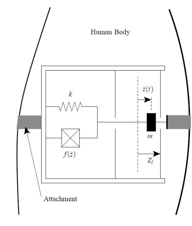
Internally we need a different approach. Instead we use an inertial generation mechanism. This is a device that can be completely encapsulated or enclosed and does not need to be anchored to 2 separate places to do work against the transducer.

So the inertial mass on a spring is doing work against the transducer, just like a Seiko kinetic watch, when the patient moves around. This has an advantage over the previous implementation is it can be completely encapsulated and therefore implanted.
Examples
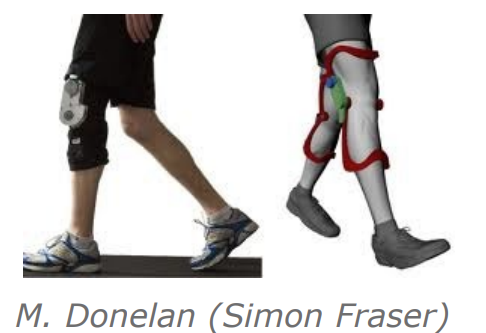
There are 2 examples of direct force driven generators, where we attach both sides and move it backwards and forwards.
- An in shoe harvester - this provides around 1W when walking
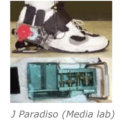
- A knee brace - this provides around 5W while walking and can make walking easier
We also have an example of an inertial harvester, a backpack where something moves up and down and power is generated. This generates around 7W while the subject walks.
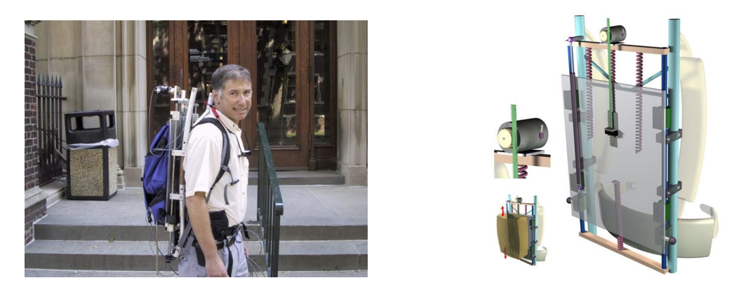
These are quite large and can cause discomfort for the patient. For smaller implementations of wearables, solar has been used.
Power from the Inertial Generators
So now we can look at how much power we can get generate from this sort of device. Newton’s 2nd law of on the mass gives us:
So the the actual frame of the device is being excited here by some motion , and the mass is moving with reference to the frame by some . We also have a damping force , which in linear mechanics is said to be proportional to velocity, the energy taken off by the transduction mechanism.
And by taking the Laplace transform we get the following transfer function:
Where:
- ,
- and
This is a simple second order transfer function. When the damping factor tends to infinity, the relative motion between mass and frame tends to zero.
We can obtain the amplitude of the transfer function by setting and finding the magnitude:
Therefore the peak relative velocity between the mass and the frame is:
And thus the actual velocity of the mass with a sinusoidal motion of is:
We can therefore integrate that over a full cycle:
Which gives us an expression for the power generated as:
Where:
We can simplify that expression and define a power at resonance (the best mode for power generation):
Where:
- is the amplitude of excitation
- is basically the size of the device - how far can the mass move inside the device
- ω is the frequency at which it is going to be excited
- is the size of the proof mass
So in order to maximise the energy harvested from this method of transduction, you must shake the device at the resonant frequency of the mass spring system.
Now, we would quite like to get this in terms of the volume of the device. Ultimately, when we specify a power supply for anything, the volume of that power supply is quite important. If we say the device is cubic, for simplicity, we get the following equation for maximum power:
Where:
- ρ is the density of the proof mass material
- is the length of one side of the cube
This can now tell us how much power could be generated from a device of a certain size, certain material and is being excited at a certain frequency. We note the very strong impact of the excitation frequency and volume of the device.
Mapping D
We have assumed that we have a power extraction mechanism that can either be piezo, electrostatic or electromagnetic. The energy taken off by the transduction mechanism, as it is proportional to the velocity . As an example, we will show how you get this from an electromagnetic type of transducer.
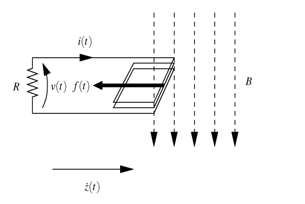
When a coil is moving in a magnetic field and pushing a current in a circuit, we have the following equations:
Therefore...
And therefore the current into a load is:
The force opposing the relative motion between mass and coil is:
And therefore the damper constant , is:
As we know how relates to damping factor and we know an optimal damping factor, we can choose magnets, coil size and number of turns, and a load resistor to maximise power dissipated in the load resistance
A Real System
A real system’s block diagram would look like so:
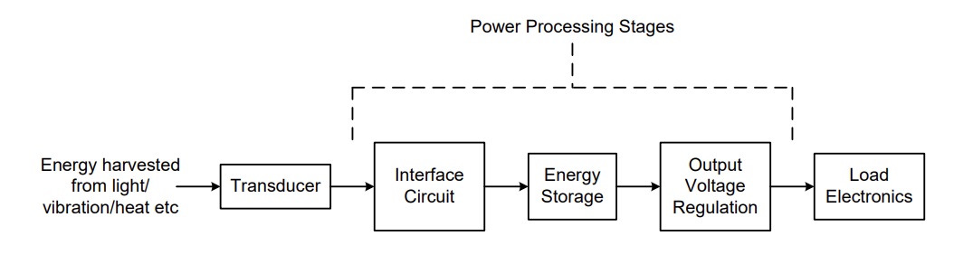
We don’t want to waste energy in a resistor, instead we want to either store it or use it to power a sensor. The usual approach for this is to interface the harvester to a battery or capacitor, with the loads connected via a regulator.
We can perform resistance emulation:
- We do this by making the interface circuit input impedance look resistive, and control it to be the same as our calculated optimal load resistance
- This can be done using a switch mode power converter
- An additional complication here is that the generator output is AC and so we need to rectify to DC, and present a resistive load.
Here is a possible solution by Stark et al from Bristol:
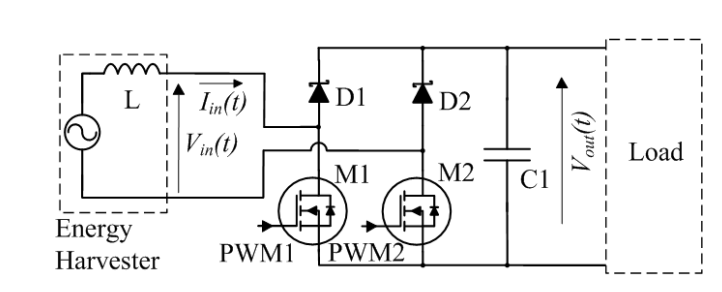
This boost rectifier interface works as follows:
- If the generated EMF from the harvester is positive and M2 was held permanently on, the system would look like a simple rectifier with one diode replaced with a MOSFET.
- However, if M1 is then pulsed using PWM, then the system looks like a boost converter
- The current in L can be controlled, increasing when M1 is turned on (flowing in a loop through the EMF, L, M1 and M2) and decreasing when M1 is turned off, pushing energy into the output capacitor C1, in a current loop through the EMF, L, D1, C1 and M2.
Thermoelectric Harvesters
Now we will look at harvesting energy using thermal gradients. This is specifically done using the Seebeck effect.
The Seebeck effect is where alternating pillars of doped material generates a current when there is a temperature difference across it
Below is a thermoelectric generator:
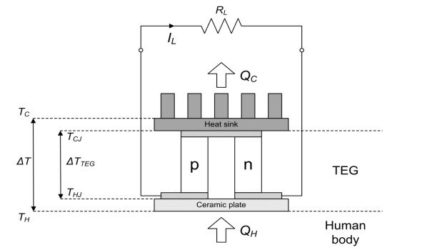
This device shows only one section but there is usually lots of these devices in series.
How does it work?
So we have many pairs of p-type and n-type materials arranged thermally in parallel and electrically in series.
When an electric current passes through the junction of 2 dissimilar semiconductor materials, heat is either absorbed or released at that junction.
Depending on the direction of the current one side of the device becomes colder, the other becomes hotter, therefore it is the thermal gradient across the device which is important to generate power.
As one side is hotter than the other, we see a tendency of those carriers, with more energy, to move from the hot side side to the cold. Because of the series configuration, this actually causes holes and electrons charge to add up and give us a current as they alternate from p to n-type material.
The voltage across one pillar is related to the temperature difference across it by the Seeback coeffecient, α, i.e:
Given a voltage we can therefore get some electrical power, but it requires a maintained temperature difference across the device. This makes sense as a wearable, where we can strap the device to the human skin and it will be heated up from the body.
Power from Thermoelectric Harvesters
Once again we would like to quantify how much power we can get out of these devices. For p-n junctions we get the following power for an electrically matched load:
Electrically Matched Load
When talking about the thermoelectric generator there are 2 impedances:
Electrical resistance because of the semiconductor material, so an internal resistance from the mechanism
Thermal resistance because there’ll be a certain amount of heat flow through the device
We match the loads because if you set the load resistor to be the same as the resistor inside a Thevenin source then we get maximum power (simple DC impedance matching).
So if we look only at the electrical impedance, and use , then we get the following equation, which is why we get the division by 4 or 2 squared.
Where refers to a Thevenin equivalent source ():
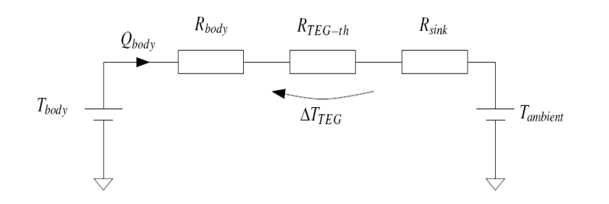
The objective is the somehow create a thermal network to maximise the amount of electrical power that my generator will produce. So we’ve got our TEG, stuck in the middle, with some temperature gradient across it and we know the bigger the temperature gradient, the larger the voltage - good for power generation.
This means we should look to make sure that the thermal impedance across the generator itself is by far the biggest of the overall impedance path.
- There’s not a lot to be done about the thermal impedance of the human body, we can’t change that - we can only change where we attach the device on the body
- BUT we can choose the size of the heat sink, if it’s bigger it has a smaller thermal impedance - it will reject heat more effectively (we want to minimise)
The problem is simple: We have 3 series resistors, the biggest resistance has the biggest voltage across it. Therefore we want to maximise .
HOWEVER there are 2 conflicting effects...
The power generated depends on the temperature difference across the device. So we want high thermal resistance. We also want low electrical resistance, because that will also increase the power.
If we want to decrease low electrical resistance we make the pillars of the p and n type materials wider and shorter (using ). However this actually IMPROVES thermal conductivity!
This means we also want a thermal impedance match:
Then as a simple potential divider we can find the temperature across the TEG:
You can work out the thermal resistances of each of the elements of the TEG and then say, if we have of them in parallel, we can rewrite it like so:
If we have in series we can get the electrical resistance of the TEG:
Manipulating all these equations allows us to differentiate power w.r.t . Bringing it all together we find an expression for the maximum power for a thermal impedance match:
For some context, the thermal resistance from the body core to the skin changes depending on activity. When exercising it can be around and while resting
A good thermoelectric material has a value of around
Comparison with Kinetic
If we calculate the volume of the TEG (the height is determined by the need to impedance match) we can calculate the power output.
We can then compare the power output to the kinetic devices…
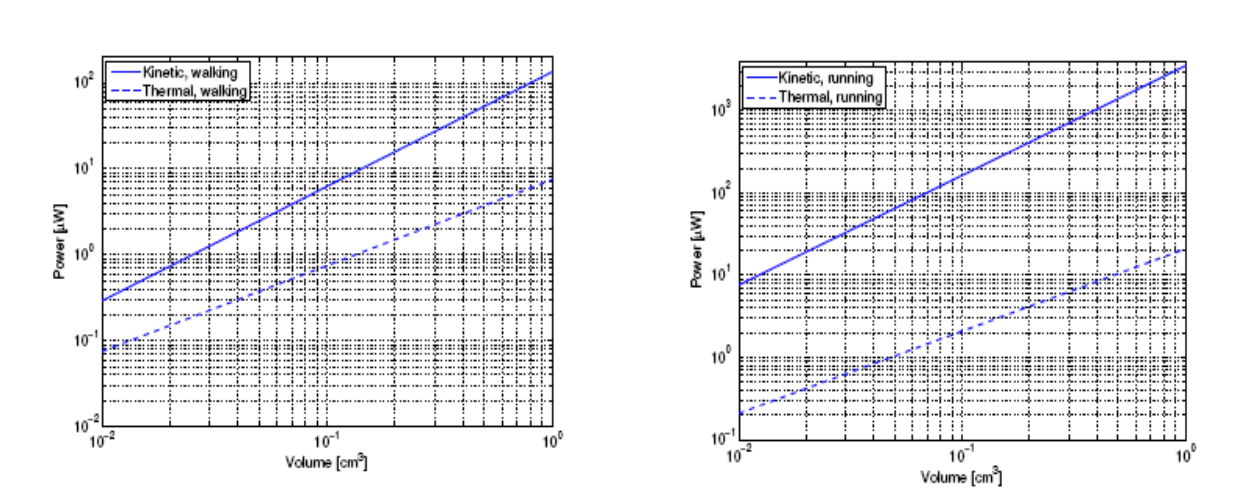
Kinetic might seem to be better overall HOWEVER these do not take into account the parasitic mechanical effects of kinetic harvesting. There actually ends up being significant loss and gradual wear of moving parts, therefore what is presented is really just an upper limit.
Also note this is a harmonic analysis, we are only looking at a single frequency, but if the patient moves at different speeds, they’re not going to be producing an excitation frequency at the resonant frequency all the time.
The thermal approach takes into account these things better, so it’s a more realistic measure of performance.
Wireless Power Transfer
The first wireless power system built in Imperial’s wireless power lab is shown below. It is essentially a loosely coupled transformer.
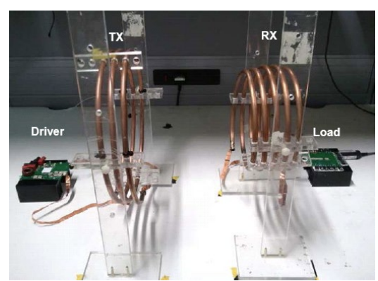
With a regular transformer you have a primary and secondary winding, and they’re wound quite tightly onto a piece of magnetically permeable material. For a low frequency transformer that might be some kind of laminated iron, and for a high frequency transformer it’s some kind of ferrite and the composition of the ferrite will change based on the operating frequency.
However if you want to charge something truly wirelessly, such that the coils are separated by just air or human tissue, then we must remove the permeable piece of laminate or ferrite.
A Regular Transformer
In a regular transformer, the iron core on which the coils are wound allows almost all of the flux generated by current in one coil to flow to the other.
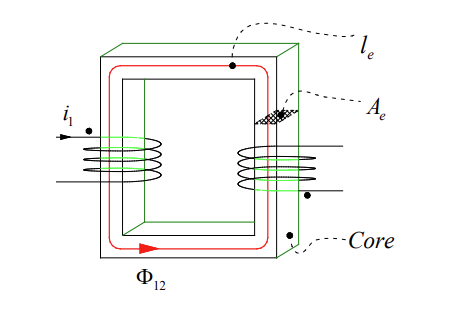
To make this a wireless power system, we basically have to cut this core down the middle and separate the two bits so that there is mobility between the transmitting side adn the receiving side.
We define a coupling factor, , as the faction of flux from one coil that links with the other coil:
A regular transformer is constructed with windings both on the magnetically permeable core, when a current runs through these windings, magnetic flux is generated. That flux runs in the core because the core is significantly more magnetically permeable than the air that surrounds it.
Almost all of the flux runs in the core and therefore it will link the primary and secondary coil.
The coupling factor is the fraction of flux produced by coil 1 that links from 1 to 2. In a transformer that might be 98 or 99%, but you can reduce it if there’s a reason to.
The problem is when we remove the core the coupling factor will actually be closer to 0 than 1
We have the following equivalent circuit for a transformer that takes into account magnetising inductance, winding losses and magnetisation losses:
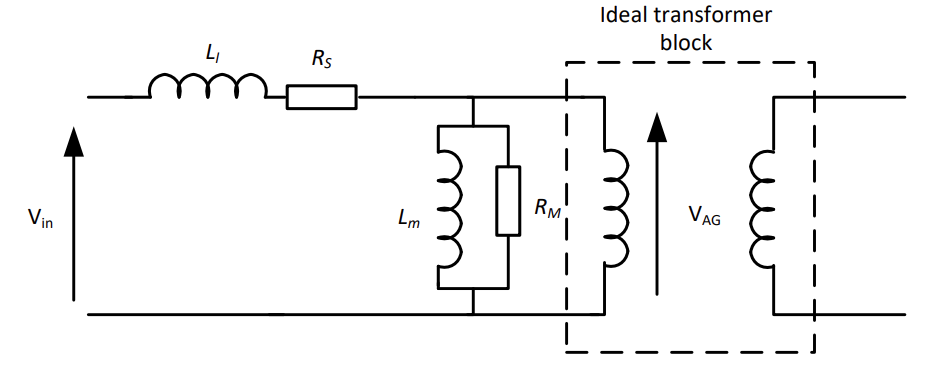
In a regular transformer the magnetising inductance is big and the leakage inductance is small.
But if we take away the core and separate the coils, the magnetising inductance falls, because we’ve taken away the closed core. The leakage inductance increases also, because most of that magnetic flux doesn’t link with the secondary, it only links with itself.
Improving Performance Without a Core
So how do we take a 99% efficient transformer that is strongly coupled and make a efficient wireless power delivery system when the coupling may be as low as 5%?
There’s a tendency to think that if coupling is 5% then efficiency is 5%, but this is not true. Actually as long as a magnetic link can be established, it does not matter if only a small fraction of it links to the secondary.
How can this be?
Well if we think the Tx coil in this picture is simply an inductor. We charge it up with current, creating a magnetic field. Then in order to change the magnetic field we have to discharge the inductor.
The key is, if we make the primary side largely with a resonant circuit, where we exchange energy between an inductor and capacitor, as long as the inductor and capacitor have low series resistance, we can just oscillate that energy back and forth in a lossless way.
Therefore it doesn’t matter that only a small fraction of it links to the load provided this magnetic field is being created and destroyed twice per cycle.
Let’s take a look at what this could look like:
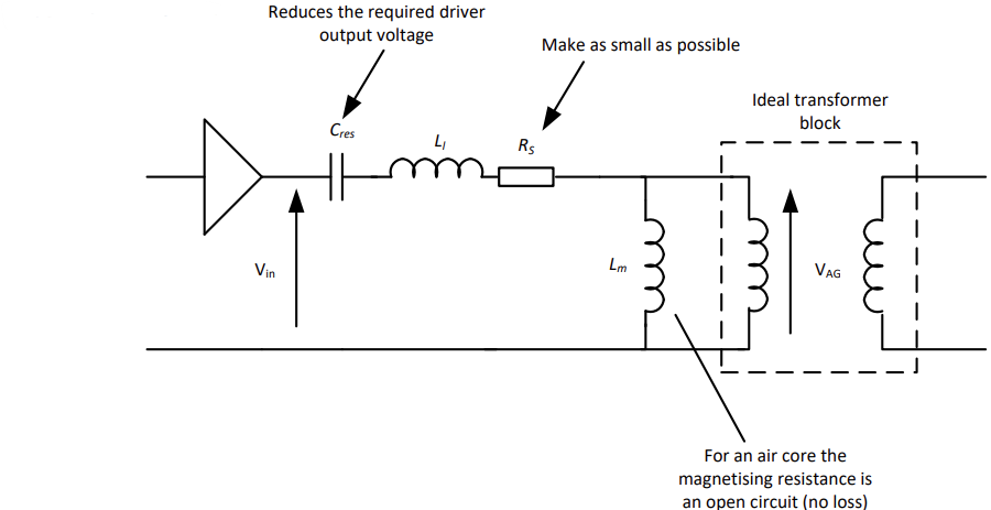
- We make the winding resistance as low as possible, to reduce losses due to real and imaginary currents
- Avoid radiation (this is not an antenna - the coupling is only magnetic) by making the primary coil electrically small
- Add a capacitor in series between the drive circuit and the primary side, to reduce the voltage output requirements of the primary side drive circuit.
- The magnetising resistance goes open circuit as air, unlike iron, has virtually no magnetisation loss.
The Real System
The real implementation is a little more like this:
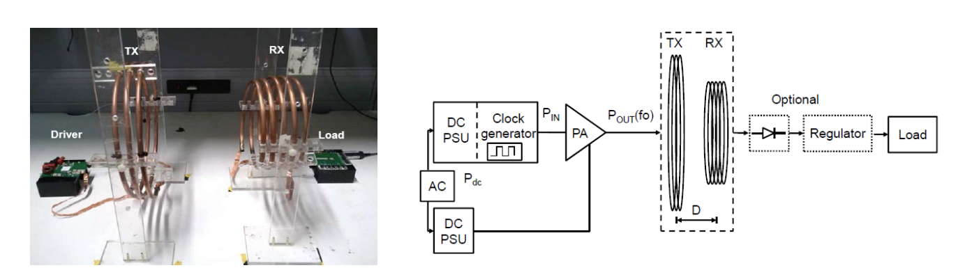
- Requires a transmit coil, receive coil, amplifier/driver (called an inverter), and a rectifier on the secondary side
- Must all be efficient
- Make the secondary resonant, so that the referred load impedance from secondary to primary is purely real, and does not detune our primary resonance.
In reality however we cannot get losses to 0, no matter how much money you spend inductors will still have some amount of series resistance and capacitors will still eventually exhibit finite values of Q factor.
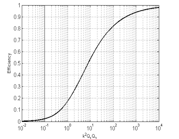
We can actually calculate the magnetic link efficiency - the maximum power that can be extracted from the secondaty divided by the power into the primary:
We note that the link efficiency depends on the quality factors of the Tx and Rx coils, so that’s related to how much loss there is in the inductance (). So if we set resistance to be small by making it out of thick copper pipe and you operate at a high frequency, your quality factor is actually quite high.
So we can have a low coupling factor as long as the quality factors are high enough. The higher we can make the quality factors, the lower values of coupling factor we can tolerate.
Rectifier for IPT Systems
We’d like the complete system to be efficient, and we note that Rx efficiency is more important than Tx.
We can briefly look at the rectifier topology, a standard half or full bridge rectifier is not suitable for two reasons:
The current drawn through a standard rectifier is pulsed (at the peak of the voltage waveform) – and thus does not look resistive, as required so not to detune our resonators
The diodes must undergo a fast reverse recovery operation, which can sum up to be very lossy when happening millions of times per second.
Our solution is a resonant rectifier:
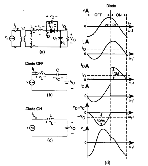
When current is flowing anticlockwise in the circuit, the inductor current flows through the capacitor in parallel with the diode (as the diode is off), increasing the reverse bias of the diode
As the current reduces and reverses direction, the capacitor voltage increases and the diode comes into conduction
As the resonant cycle continues, the diode current drops and the diode falls out of conduction as the parallel capacitor again conducts
Turn off process is controlled - no reverse recovery losses
Human Compatibility for IPT
We’ve talked about encapsulation, but now we also have to consider that we will eb subjecting the body to some high frequency magnetic and electric fields.
These can cause heating of tissues and nerve and muscle stimulation so care needs to be taken to ensure human compatibility for an IPT system
Non-thermal effects of EM fields are important < 50MHz: Stimulation of muscles, nerves and sensory organs (induced E-field in body)
- Not any higher because it becomes too fast for the body to even react to the stimuli
Thermal effects of EM fields are important at > 100kHz: Tissue heating due to energy absorption by conductive human tissue
- Eddy current heating
- Dielectric heating
Also there is heating due to dissipation in the implanted Rx coil
Regulation
The ICNIRP limits are adopted by the WHO, they define limits into law for different equipment types and exposure scenarios to EM radiation. The limits are split into 2 main categories:
The basic restrictions (BRs) or ELVs:
- Must not be exceeded
- Non-thermal effects: induced E-field in the body
- Thermal effects: SAR (W/kg)
- Hard-to-measure quantities inside the body, but computational EM simulations based on FEM can be performed with accurate human body models to evaluate compliance.
The reference levels (RLs) or action levels (ALs):
- Unperturbed (no human body present) external E- and H-field values that can be easily measured.
- If RLs are not exceeded, then no need to demonstrate compliance with BRs.
- If RLs are exceeded, it does not necessarily mean that BRs are exceeded; a system can still be safe but requires EM simulations to show BR compliance.