- Have Revised
Introduction
This lecture will focus specifically on the fundamentals of how you would design a stimulator, the nuts and bolts and the fundamentals behind stimulation circuit design.
So as discussed in 5.1, we’ve covered the following applications of stimulation. They typically come in 2 types:
Muscle Stimulation
- Cardiac Stimulation
- Pacemaker
- Defibrillator
- FES
- Cardiac Stimulation
Neural Stimulation
- CNS
- DBS
- Sensory prosthesis (cochlear implant, retinal implant, vestibular implant)
- PNS
- VNS for epilepsy
- Motor control (for FES)
- CNS
Stimulation Circuit Examples
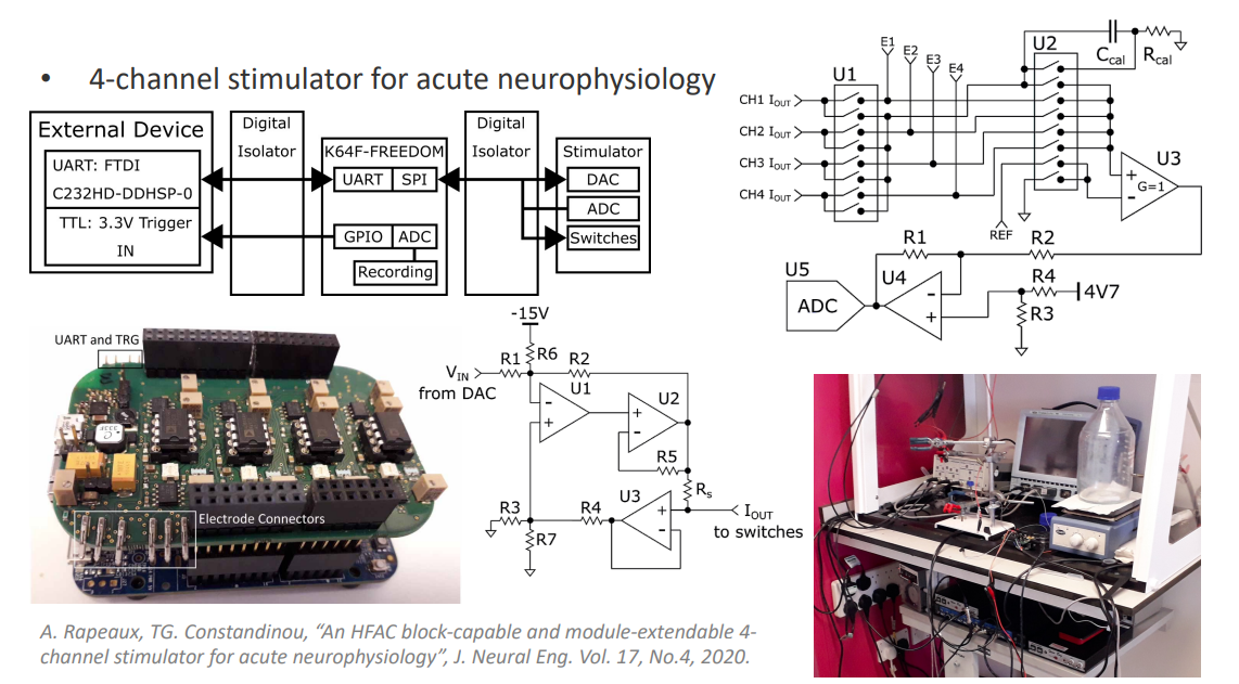
This circuit is designed to extract a nerve from an animal which can stay alive for 12 hours and then try out different stimulation waveforms on it, to find the most efficient way of stimulating that nerve.
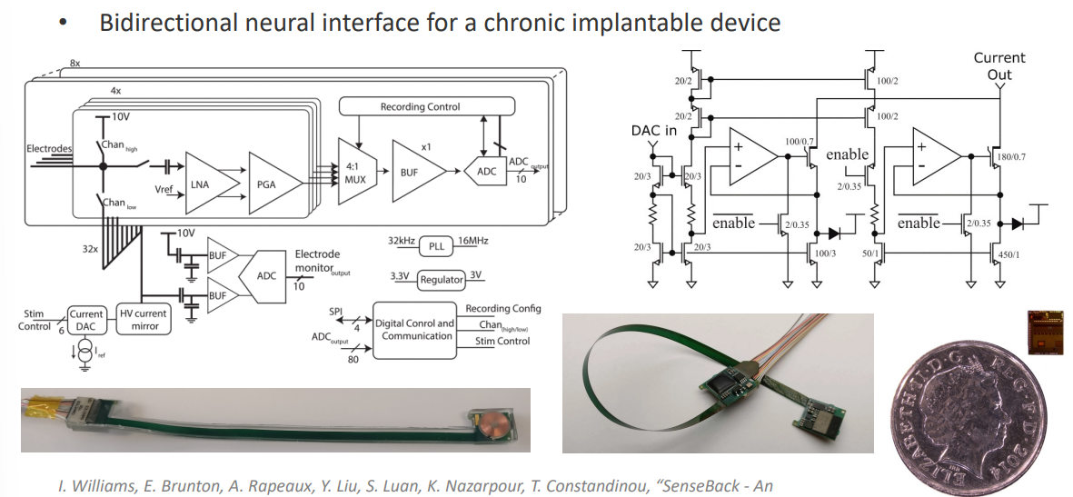
This is another designed implantable chip that had a recording pathway and a stimulation circuit. The idea is that you can record activity from the NS but also stimulate activity at the same time.
In this lecture we are going to cover these types of circuits, and we go about designing them.
Electrode Types
So when we talk about stimulation circuits, what are we actually stimulating? Well we are trying to communicate an electronic current to an ionic current in the tissue.
This translation between electrons and ions are done by electrodes.
We have different styles of electrodes. This electrode is used for cochlear implants in the brain. You can use that to stimulate the brain directly.
- CNS - Penetrating Electrodes
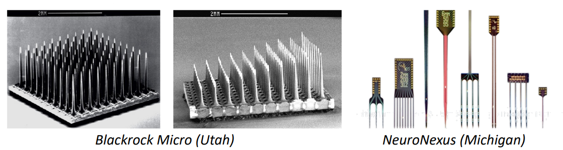
We also have these types of electrodes which typically wrap around nerves or they can be threaded through nerves.
- PNS - Cuff/ LIFE/ TIME
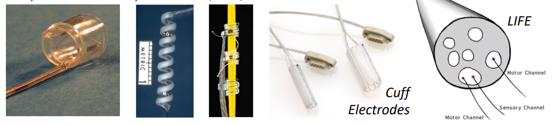
Other types of electrodes include:
- Cochlear Implant Electrodes
- Retinal Implant Electrodes
- DBS Electrodes
- Electrodes for Cardiac Rhythm
And many others...
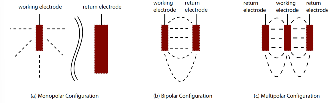
Electrode Configurations
So now we’ve spoken about electrodes, what are the different ways in which we can configure electrodes in order to achieve stimulation.
Fundamentally we need 2 electrodes in order to stimulate. Because if we have a current source, we push that current into tissue, we then need to get that circuit back so that we can close our circuit and pass it to ground.
Monopolar Configuration, with return electrode placed at a distance from the working electrode and with a larger surface area
- So we have one big shared electrode
- If we had a 10 channel system we would have 10 small electrodes and 1 big one for the reference
Bipolar configuration, with dedicated electrode pairs per channel
- So for every site that we want to stimulate with a pair of electrodes
- Therefore for 10 channels we need 20 electrodes
Multipolar configuration
- This is more complicated
- A scheme by which you actually stimulate through lots of electrodes
- For example in this one (on the right), 1 electrode is the cathode and 2 which are the anode, so basically part of the current is going between one pair of electrodes
At the end of the day you just have KCL, so the amount of current going into the tissue has to equal the amount of current going out of the tissue.
In the majority of devices we use the Monopolar Configuration
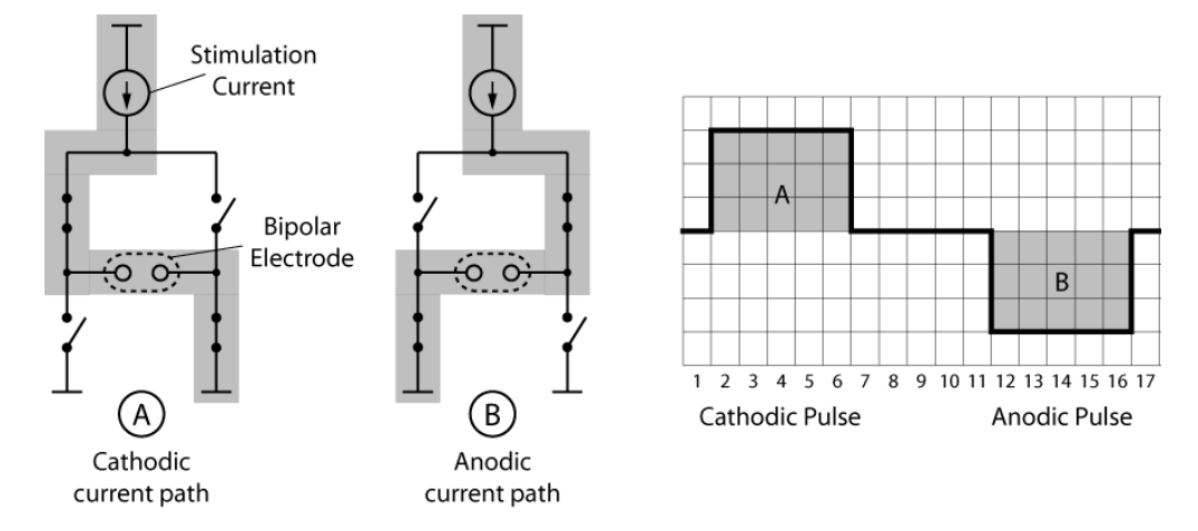
Electrode / Electrolyte Interface Model
We’ve seen this model before.
A complex electrochemical reaction occurs at the electrode/electrolyte interface model.
- Current flows cia electrons in metal but via ions in solution
- Any charge buildup can lead to non-reversible faradaic reactions (i.e. electrodes dissolving, gas formation, variation of pH, etc)
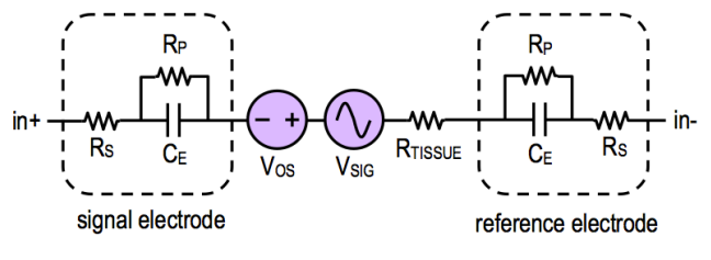
Where:
- = Solution spreading resistance
- = Faradaic charge transfer resistance
- = Capacitive charge transfer via the interface capacitance (approx. )
Note: the elements and can be lumped together
Component values are dependent on the electrode’s material and the tissue/electrolyte.
The electrode impedance is frequency dependent - this is due to the capacitor.
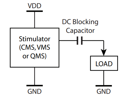
Waveform Profiles
Fundamentally, in order to stimulate tissue, we need to send a pulse into that tissue.
However it’s very important that whatever charge we inject into the tissue, we then pull out of the tissue, there must never be a net charge flow into the tissue or out of the tissue, otherwise we have DC current. (area under graph above and below zero should be equal)
Why do we NOT want DC current?
Our electrodes will start to dissolve and bad things will happen
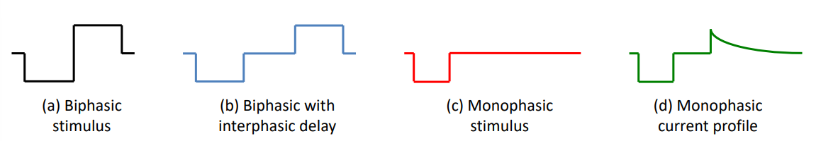
So to stimulate the tissue we would just need monphasic, but in order to pull the charge back out we would use biphasic, because it’s 2nd phase is pulling it back out.
So let’s go into more detail:
- Stimulus must be charge balanced (i.e. net charge is zero)
- Monophasic waveforms rely on passive discharge (i.e capacitively coupled)
- Stimulation waveforms are typically biphasic (with cathodic & anodic phases)
- Cathodic phase: first pulse is for activation
- Anodic phase: second pulse is for balancing
- Additional considerations
- Interphasic delay often used to prevent anodic phase blocking activation - i.e if we pull current in and out straight away, we might not stimulate the tissue, so add delay
- Shorting phase often used to remove residual charge (every few cycles)
We can take a closer look at a sample waveform, which has multiple phases.
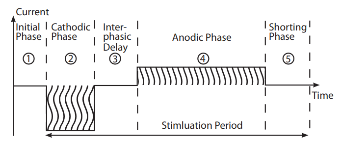
Things to note:
- The positive currents and negative currents are different magnitudes, this is because sometimes it’s desirable for your stimulation phase to have larger current over less time, but your balancing phase to have smaller current over longer time.
- This is called an Asymmetric waveform, it’s particularly good for a thing called fatigue.
- If you stimulate the tissue really, really quickly, the tissue will get tired after some time. So there’s a maximum rate at which we can stimulate tissue. We can limit this by using asymmetric waveforms.
There are lots of different types of waveforms but generally (≈ 90%) devices use monophasic if you don’t care about speed of stimulation and you do it through a capacitor. If you want to stimulate very quickly you use biphasic.
NOTE: Asymmetric waveforms are not applicable to high channel/high refresh stimulation
This is because the overall stimulation period gets much longer, and we can only stimulate one channel at a time (if we pump current into different electrodes we’ll get crosstalk between them). So we can’t stimulate concurrently two sets of channels - therefore we have to do time division multiplexing.
Why do we like perfect square pulses?
- Easier to implement
- It’s easier to monitor the amount of charge (simple current * time)
Stimulation Circuits / Design
Now let’s move on to the actual circuits, we’ll look at specific examples, design principles, requirements and applications.
Stimulation Circuit Requirements
Dynamic Range
- The minimum to maximum stimulus or magnitude
- this depends on electrode - the smaller the electrode, the closer the electrode is to the tissue and therefore less current is needed
- Can range from -
Needs to work with Electrode Variability
- We need to know the type of electrode we’re stimulating so we can design our power supply to accomodate the voltage drop across the electrode impedance ()
- The larger the electrode, the lower the impedance
- Can range from -
Digitally-programmable
Should ensure charge balancing
- i.e Anodic/cathodic matching, so the stimulus does not exceed the maximum charge density of the electrode material
- typically % mismatch
Energy efficiency
- Should be energy efficient, good battery lifetime / charge cucles
- Stimulation efficiency = power consumed at electrode / total power consumed
Reliable
- Must be reliable over a period of years (if plantable)
Stimulator System Design
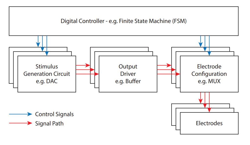
Let’s break down this design fundamentally:
- Stimulus Generation Circuit: A circuit which generates a quantity
- Output Driver (Buffer): A circuit that matches the impedance of the electrode so that it can drive that current of voltage into the tissue
- Electrode Configuration (MUX): Switches that can steer that current or voltage to different electrodes
- Electrodes
- Digital Controller: All components controlled with this, could be a micro-controller, FPGA, custom FSM, etc. It performs the digital timing and controlling the switches.
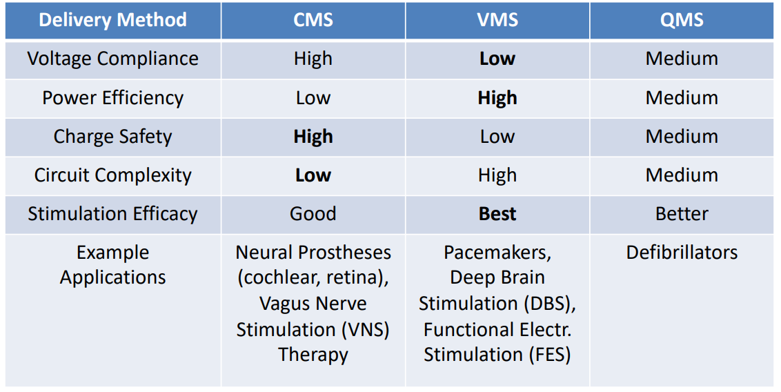
Methods of Charge Delivery
It’s possible to deliver charge to tissue, via circuits changing the stimulus, in different ways.
Action potentials can be generated by Electrical Neural Stimulation, triggered by injecting a charge packet to the extracellular space.
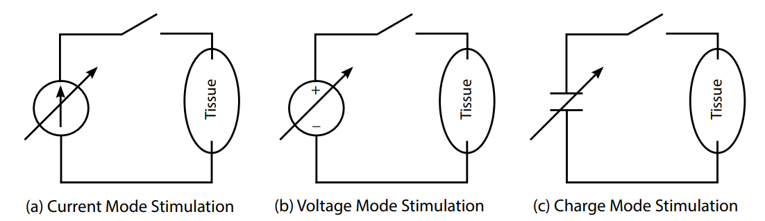
Here we see 3 types of charge delivery, using programmable current, voltage and charge sources:
- Voltage-Mode: fixed voltage, monitor the current, control the duration
- Current-Mode: fixed current, control the duration
- Charge-Mode: fixed capacitor, charge to fixed voltage, then discharge to stimulus
NOTE: The most common and safe method is current mode
Current-Mode Stimulus Generation
So how do we generate a current mode signal?
It’s actually very simple. We use something like a current mirror. It’s a binary-weighted current mirror
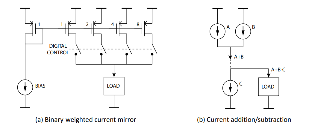
A binary-weighted current mirror is a current mirror type circuit that is used for DAC. Here’s a basic idea of how it works:
- We supply a bias current (say )
- We get in branch 1, in branch 2, in branch 3 and in branch 4
- then by controlling the switches we can make whatever current we want
- and we can add and subtract current by connecting current sources together
The 2nd thing we need to worry about is when we’re doing a current mode stimulator, is what actually drives the tissue.
If we’re designing a current source our ideal O/P resistance is infinity
In reality it doesn’t have to be infinite, it just needs to be much, much higher than the load resistance. This is where we go back to the electrode, so if we have a electrode, you need your current source to have a resistance.
So there are 3 classes of O/P stages:
A simple current mirror
- This supplies to load around 10 -
Cascode current mirror
- This supplies something like 10 -
Regulated cascode
- This supplies around
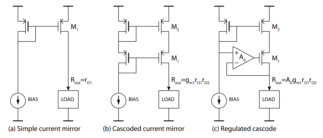
The disadvantage of using the regulated cascode rather than a simple current mirror is that we’re losing voltage. So therefore it is more power consuming as we must consider this voltage headroom by adding additional voltage to compensate.
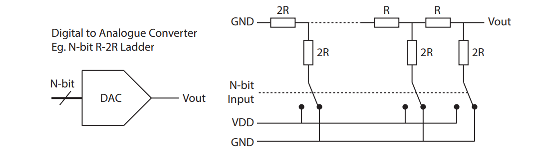
Voltage-Mode Stimulus Generation
So how do we design a voltage stimulation circuit?
We would use something like a DAC, like an R-2R Ladder,to generate the stimulus, which is an O/P voltage that represents the stimulation quantity we want to deliver to the tissue.
The challenges with this method include:
Need to maintain the output current within allowable limits
- i.e. electrode charge density
Monitoring charge delivered to the electrode
- When we apply a voltage to out electrodes, we can’t monitor the amount of charge delivered
- The solution is a microcontroller with an ADC and a series resistor
- We can measure the voltage drop over that resistor and get the current from there by integrating the current over time.
- This gives us the charge delivered to the tissue
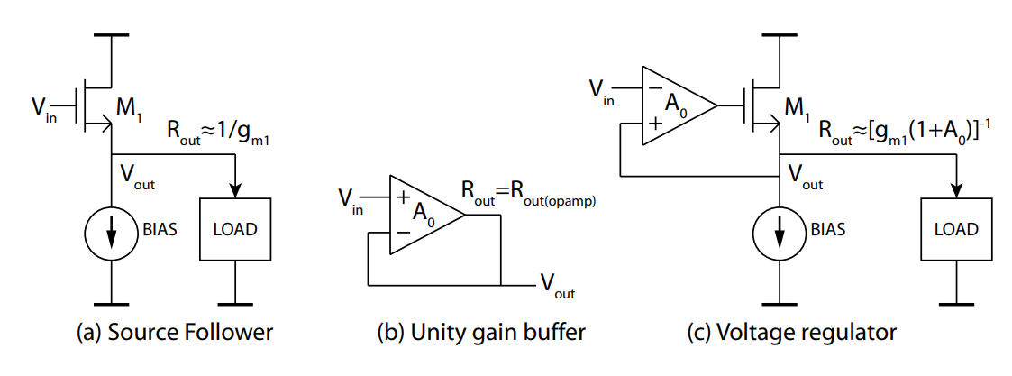
Now, in order to deliver voltage effectively to a resistance, we need a relatively LOW resistance compared to the load (opposite of CM).
So we have 3 possible solutions for our Voltage Output Stage (Buffer):
Source follower
- O/P resistance of about
Unity gain buffer
- O/P resistance of about
Voltage regulator
- O/P resistance of about 0.1 -
Charge-Mode Stimulus Generation
Charge delivery is quite simple, we charge up a capacitor to the stimulation voltage and then dump it on the tissue. This stimulation voltage is set by a DAC or voltage reference.
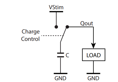
The challenges with this method include:
Incomplete charge delivery due to charge sharing
Limited charge stimulus capacity
- i.e requiring a large capacitance
Comparison of 3 Types
Charge Balancing
So how do we charge balance?
One thing we normally do is we always connect our stimulator onto our electrode through a capacitor. The beauty of this is that we never have DC current flow through our capacitor.
Some notes:
- It’s the easiest method
- Desirable for safety (single component failure)
- Commonly used for cochlear implants
Another way we can charge balance is by reusing our current source. So if we have a single current source and we implement what’s known as a H-bridge, depending on how we close and open out our switches, we can reverse our current.
LHS current moving from left to left. RHS current is moving from right to left.
Some notes:
- If you’re implementing a stimulator using an anodic current source and current sink, then there’s the problem of mismatch between the two.
- Whereas here you’re reusing the same current source
We also can have a circuit that basically shorts our electrodes together, and does what we call passive discharging.
Some notes:
- This is the most commonly applied technique to remove residual charge - typically after each stimulation cycle (or after a series of cycles)
- RC time constant (electrode and short discharge path) however can significantly increase the overall stimulation timing
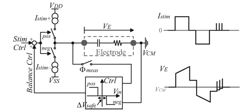
The final example is where we do a crude charge balancing. So we stimulate, then take out our current, but there might be a bit of residual charge. It’s not precisely balanced. So we can look at the voltage on the electrodes and if that voltage is not 0 we can add a few pulses to bring it to 0.
Some notes:
- So we measure delivered charge in cathodic phase, and adjust anodic phase accordingly
- After stimulation cycle is complete (after both phases), monitoring the net charge and compensating using discrete compensating pulses